PIC Geliştirme Kartı
CompletedMy first board design: a PIC18F46K22 development board with an LCD, zero-cross detection and triac-based AC load control. Drawn in Proteus from schematic to PCB.
My first board
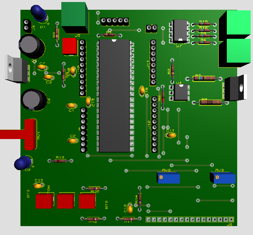
This is the first electronic board I drew end to end, from schematic to PCB. I designed it in Proteus. The goal was to try a microcontroller's basic jobs, such as analog reading, a display, buttons and AC load control, on a single board.
What's on the board
- Microcontroller: PIC18F46K22 with an external crystal oscillator
- Power block: 5 V from a 9 V input through a 7805 regulator, with filter capacitors and a power LED
- LCD: a 16×2 character display showing the ADC value and voltage read from a potentiometer (e.g. "ADC: 1022 · Voltage: 4.99")
- Voltage adjuster: an RC-filtered potentiometer on an ADC input
- User input: 3 buttons with pull-up resistors and debounce capacitors
- Zero-cross detection: two PC817 optocouplers detect the positive and negative half-cycles of the AC sine separately
- AC load control: a triac isolated by a MOC3021 opto-triac; together with zero-cross timing it allows phase-angle control (dimming)
- Expansion: every port is broken out to pin headers
Schematic
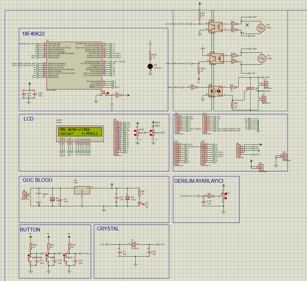
The schematic is split into blocks: microcontroller, LCD, power, voltage adjuster, buttons, crystal and the AC control section.
PCB
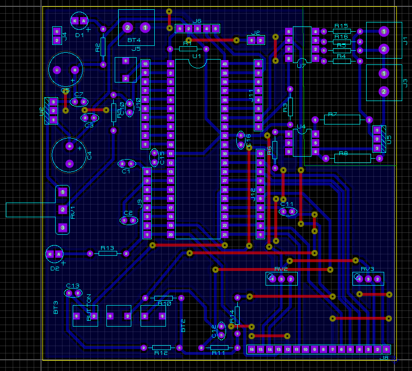
The board is a two-layer design. The microcontroller sits in the middle, the power block on the left and the AC side (optocouplers and triac) in the top-right corner, keeping the high-voltage side away from the rest of the board.