ESP32 Röle Kontrol Kartı
In progressAn ESP32 relay control board that switches four separate loads, with every channel isolated by an optocoupler. The schematic is done; PCB layout is in progress.
Project
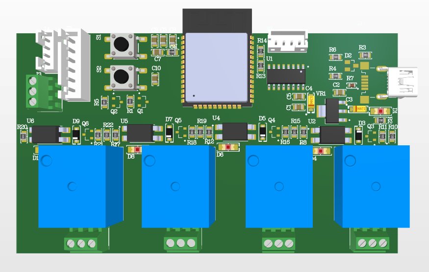
A 4-channel relay control board built around an ESP32. Each channel switches its own independent load, and the ESP32's Wi-Fi and Bluetooth will let the board be controlled remotely. The board can be both powered and programmed over USB-C.
Circuit
- Main controller: ESP32-WROOM-32E (16 MB flash)
- Programming: a CH340C USB-to-serial converter and an automatic boot/reset circuit with two SS8050 transistors, so no buttons are needed to upload code; EN and BOOT buttons are still there
- Protection: SM712 TVS diode for ESD protection on the USB data lines
- Power: LM1117 regulating 5 V down to 3.3 V, plus a power LED
- On every relay channel: a PC817 optocoupler isolating the ESP32 from the relay side, an SS8050 transistor relay driver, a 1N4007 flyback diode and a status LED
- Outputs: a screw terminal with COM / NC / NO for each relay
- Expansion: UART, I2C (with 4.7 kΩ pull-ups), SPI and power connectors
Status
The schematic is finished in Altium Designer (October 2026, revision V1). The 3D view above is a draft of the component placement; the next step is routing the PCB and manufacturing the board.